


Next: local illumination models
Up: Introduction
Previous: Introduction
Contents
Index
Our goal is the approximation of real world's objects appearance for the visual sense - thus we should gain deeper knowledge about this sense first.
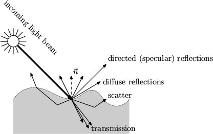
The visual sense provides us with information about objects of our environment by analyzing light which had been in interaction with them. If we are going to imitate the visual impressions of the objects for getting a photo-realistic image from a virtual representation of these objects we have to simulate the interactions/modifications of the light on its way from a source to the receptor (human eyes or a camera). Badly for us this is quite a very difficult task because of the amount of possible interactions between light and matter as fig. 1 shows.
Figure 1:
interactions between light and matter
 |
Important interactions are:
- specular reflection
- Specular or directed reflections are reflections on even surfaces; the angle between the norm vector
 of the surface and the incoming light beam equals the angle between the norm vector and the outgoing/reflected light beams. This component is strong for shiny materials like metals or glass.
- diffuse reflection
- is caused by the rough microstructure of real surfaces. Diffuse reflections illuminate wider parts of the objects as the specular reflection does; diffuse reflections lead to a diffuse or ambiental illumination - it's very important to take this into account, otherwise the generated images will be too dark (imagine a scene of a room with light falling through the window: with pure specular reflections all parts not being hidden by reflections from shiny surfaces would be black!)
- transmission
- is typical for transparent materials; the effect that incoming light changes its direction when passing material boundaries is known as the refraction law of Snellius.
- scatter
- Scattered light illuminates the interior of objects; an example is the visibility of light beams in dusty air. Rendering experiments showed that scattered light is also important when rendering human skin (without considering scattered components it would look like plastic).
- fluorescence
- and other complex interactions between the electrons of an atom and the light are mostly fully neglected.
Theoretically most of these interactions could be modeled using the wave equations derived from Maxwell's laws (many interactions between the electron hull and the light couldn't be described without quantum physic models!). The reason why today's rendering algorithm aren't based on this approach is quite and simply computational efficiency (plus numeric problems occurring especially when solving wave equation systems like this on computers).
Instead of trying to simulate as exactly as possible CG frontiers have chosen a very engineer-alike solution: they searched (or better: are still searching...) for approximation models which imitate these effects as exactly as possible. The difference: I assume that you've been a normal child and went to a normal school, so I'm hopefully not wrong when expecting that your good old physic teacher didn't introduce you to the wonderful world of linear optics by writing Maxwell's laws at the blackboard. Typically they start with the declaration of the following simplifications:
- Light is assumed to have its origin from a point source located in infinite distance from the observer.
- So the wavefront of the light could be assumed as planar.
- Following these assumptions light propagation could be modeled by the mathematical abstraction of a ray.
Using the ray approximation and the reflection and refraction laws they could demonstrate the principles of mirrors and lens systems up to microscopes and telescopes. After all, this approximation is good enough for designing such complex systems! But there is another common simplification regarding light in linear optic discussions: most real world light sources (neglecting special cases like Laser's or filtered light here) doesn't emit light with a single wavelength but a superposition of light waves with individual wavelengths. If you plot the emitted power with respect to the wavelength you'll get the emission spectrum of the light source. The dominant wavelength rules the color (hue) of the light, the relative sharpness of the envelope rules the saturation and the overall intensity rules the value (v). It's typical for today's renderer that this spectrum is reduced to the color of the light described by a color model ; one disadvantage of this simplification is that dispersion effects would be fully neglected.
Next: local illumination models
Up: Introduction
Previous: Introduction
Contents
Index
Rüdiger Knörig
2002-06-09