Next: Bibliography
Up: Algorithm used in photo-realistic
Previous: Ray-tracing
Contents
Index
- artefacts
- Differences between a rendered image
and a real one captured by a camera from a real scene / rendering
errors caused by the simplifications used e.g. for the illumination
models. A famous test for evaluating a renderer is the cornell box .
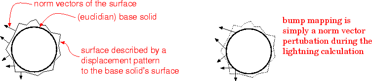
- bump mapping
- Simulation of uneven surfaces by
pertubating the important norm vector in the surface points:
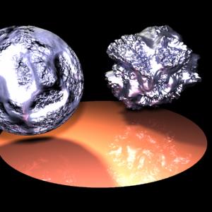
Figure 6 shows the disadvantage of this
approach: it doesn't change the shape of the projected object.
Figure 6:
left: bump mapping right: a real surface (rendered with lightflow)
 |
- CAD
- Computer Aided Design
- CAM
- Computer Aided Manufacting
- environmental mapping
- Faking of
interreflections for local illumination models; an image rendered from the position of the object is wrapped around the object by
standard texture mapping techniques. Notice that this approach cannot handle
recursive interreflections and may produce artefacts for multiple
interreflections.
- color model
- Any system for representing colors as ordered
sets of numbers. The most common color models are
- RGB
- describes a color as a weighted superposition of the base colors red,green,blue; additive superposition and therefore used for computer/TV screens
- CMYK
- color model that describes each color in terms of the
quantity of each secondary color (cyan, magenta, yellow), and
"key" (black) it contains. The CMYK system is used for
printing. For mixing of pigments, it is better to use the
secondary colors, since they mix subtractively instead of
additively. The secondary colors of light are cyan, magenta
and yellow, which correspond to the primary colours of pigment
(blue, red and yellow). In addition, although black could be
obtained by mixing these three in equal proportions, in
four-colour printing it always has its own ink. This gives
the CMYK model. The K stands for "Key' or 'blacK,' so as not
to cause confusion with the B in RGB. (cited from The Free On-line Dictionary of Computing)
- HSV
- (the mentioned hue-saturation-value-model).
- Computer Graphics
- Conversion of a mathematic/geometric object
descriptions into visual representations (actually more or less 2D-projection like images)
which approximate the visual impressions of real objects using computers.
- Dispersion
- Spreading of the spectral components due to the wavelength dependency of refraction (see refraction law)
- norm vector
- Vector being orthogonal to the surface, could be defined as the cross product between the surface gradients:
![\begin{displaymath}
\vec{n}=\left(\begin{array}{c} \ParDer[u]{f_x(u,v)} \Par...
...arDer[v]{f_y(u,v)} \ParDer[v]{f_z(u,v)} \end{array}\right)
\end{displaymath}](img18.png) |
(3) |
In many cases this vector is assumed to be orthonormal (
 ).
).
- radiosity
-
While raytracing simulates light propagation by tracing sample rays
through the scene radiosity evaluates the energy transport caused by
the emmision and absorption of radiation in closed systems. Originally
it had been developt for calculating temperatures of objects nearby
thermal radiation sources. Later then its capability for calculating
diffuse/diffuse interreflection has been discovered and it became the
second popular global illumination model. For more information
regarding the differences between raytracing and radiosity have a look
at this page.
- rendering
- Performing the conversion of an object description into a visual representation. (see
 Computer Graphics)
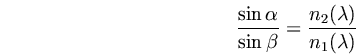
- refraction law of Snellius
- May
 be the angle between the norm vector and the incoming light beam and
  the angle between the norm vector and the refracted light beam and
  the refraction index of the first material and therefore
  the refraction index of the second material as functions from the wavelength
  (dispersion!), then the refraction law of Snellius rules:
 |
(4) |
Next: Bibliography
Up: Algorithm used in photo-realistic
Previous: Ray-tracing
Contents
Index
Rüdiger Knörig
2002-06-09