Introduction
If you are familiar with raytracers like PovRay the basic concept of LightFlow may be a bit strange to you: LightFlow defines itself as a rendering extension
to object-oriented computer languages (currently supported are Python and C++) - but it's the same approach used in the famous RenderMan-Tool-Package
(used for example in the movie "A toy's story"!).
Don't worry, it's very simple: The basic idea is that your program communicates via a proxy with the renderer. A proxy is something which acts for you (e.g. an
internet proxy is a service which tries to get your desired web pages), so the proxy here supplies your commands to the renderer. This has two big advantages:
- A clean separation between the implementation of the renderer and your program.
- The renderer hasn't to be a local process; rendering could performed by a remote process - the only change in your program would be a directive to the proxy
for using the desired renderer process.
Unfortunately the remote rendering option isn't available in the free version of LightFlow, but this is the only restriction I remember. In the next section(s) I'm going to
introduce you to the usage of LightFlow by some examples. I had chosen C++ for this purpose because IMHO this should be more in common than Python
(besides, programming with the LightFlow tools will enhance your OOP or at least your C++ skills!).
Installation
Before every usage the goods ruled the installation. Go & get lightlow from its homepage or from here.
With the base package I successfully installed the Python API, but the C++ API required (at least on the SuSE dist.) some handworks. So go and follow the installation
instructions located at the end of the raytracing section of my homepage.
If you succeed you should be able to compile some of the C++ examples there (try the tree or the mechanic die).
A first step
Let's get concrete: In this section I will explain you the basic techniques for using LightFlow from a C++ program. We will start with a very simple
scene to which we add more and more feature later. I assume that you're working in a Unix-like environment where the basic development tools (C++ -compiler
,make,..) are available.
I emphasize that you should create a new directory for this project for clarity. Because we're going to write a C++ program which needs a compilation step
I suggest the usage of a Makefile for simplifying the compilation. So invoke your favorite source editor (I prefer the emacs because it's superb for editing sources)
and hack in the source of the Makefile depicted below (of course without the explanations!).
It's quite simple: the definition term specifies some macros used e.g. for specifying the used compiler. This makes adaptions & changes much easier.
The most important part of a Makefile are the creation rules. These start with the specification of the target to make, e.g. "simplescene:". In the same line follows
the dependencies of the target, e.g. the sources of the program. Make will recreate the target if one of the dependencies is younger than the target (e.g. simplescene
will be recreated if main.cpp (the dependency!) has been edited since the last compilation). The following line(s) have to start with a <Tab>!
They describe the necessary steps to create the target. Per default the call of make without arguments will create the first target. For our makefile here this is
ball.jpg - a JPEG-file with a rendered image. Unfortunately LightFlow supports only two image formats, an internal format and the aged .tga-Format. So we create
the JPEG picture from a rendered TGA picture using the powerful convert-utility (have a look at the man-pages of convert! You will be surprised by the
possibilities this tool offers!). So the dependency of the JPEG picture is the TGA picture. The TGA picture itself will be created by our C++-program simplescene,
which in turn will be created from the source file main.cpp. It's important to link against the lightflow libraries here (-lLightflow directive!).
Creating the framework
Let's start with the C++-program source. Create a new file named main.cpp and type in the following lines:
 #include <Lightflow/LfLocalSceneProxy.h>
 #include <math.h>

 int main()
 {
    // create a new proxy
    LfLocalSceneProxy *s = new LfLocalSceneProxy();
    // this is a container object for storing the arguments passed to
    // the renderer via the proxy
    LfArgList list;

    return 0;
 }
At the beginning we include the math library and Lightflow/LfLocalSceneProxy.h, which contains most of the necessary classes.
In the following main procedure a proxy object (s) is being created first. As you may conclude from the class name this is a proxy
connecting to a local renderer only. Its constructor accept the size of the texture buffer as an optional argument, but we leave it at its defaults
for the moment. The next object being created (list) is a container object. These objects are used for passing arguments to the renderer
via the proxy object. You'll see later that this way make it possible to specify only the relevant options without being forced to specify all arguments.
At the beginning was the light...
What's a philosopher? Someone who is sitting in a dark room discussing the possibility that there may be another person in the room for hours. What's an
engineer? Someone who's answering this question by hitting the light switch. Enough jokes - but it should be clear that the ability to "see" something is strictly
bounded to the existence of a light source. So we start our scene with a light. Add these lines behind the creation of the list object:
    // define a light
    list.Reset();
    list << "position" << LfVector3(-4,-7,6);
    list << "color" << LfColor(450*1.0,450*1.0,450*0.8);
    LfInt light = s->NewLight("soft",list);
    s->LightOn(light);
Step-by-step: our first action is to invoke the reset()-Method of the list object. This should be done before every new usage of the container.
Next we specify two parameters of the light: the position and the color (+strength). For doing that we feed the name of the parameter (e.g. "position")
and the parameter value to the list object. The position value is given as a coordinate triple in 3D space, the color as a weighted RGB (red,green,blue)
triple; the higher the color value, the stronger the lightsource. In the example the strength (450) has been separated from the basic RGB triple. For both values
the LfVector3-class is used for the representation. You will see later that Lightflow defined some more datatypes but not so much that you get lost.
In the next code line we advise the renderer via the proxy to create a light; for this purpose the proxy offers the NewLight method. It takes two arguments:
the type of the light ("soft" would be a point light drawing soft shadows) and the parameters of the light supplied via the list object. If you ask yourself where to
get information about available lights or parameter options: the Lightflow package contains a HTML documentation (one for the Python binding (subdir PM) and
one for the C++-binding (subdir CS)). I installed these doc-dirs under /usr/doc/Lightflow and added the index.html's to my bookmarks. Browsing these documentations
is the best (and IMHO) only way to explore the possibilities of Lightflow.
But back to the source: the NewLight-Method returns an integer handle to the created light (remember: these objects will be created in the renderer, not in the
application you're writing!). The freshly created light has to be switched on (it seems that Lightflow provides or should provide features for dynamic scenes, but I've found
no documentation for this :-( ).
Something to made the ball from
Now we are able to see something by overcoming the total darkness, but there is still nothing to look at. For making the ball Lightflow needs two information about it:
- the geometry (position,shape,orientation,...)
- the appereance (shiny,dull,color,transparency,fraction index,...)
Traditionally the appereance of the objects is defined by the material from which these objects are made. A wooden ball is simply a sphere made from the material "wood".
Related to the appereance Lightflow defines these attributes:
- Material
- A material defines the reaction between object's surface and the light. Lightflow provides a lot of material classes (standard,physicals) with
individual strengths and weaknesses.
- Interior
- The interior defines the behavior of the light inside of the object. This doesn't mean phenomena like refraction or so (these will be described by
material attributes) but a dusty appereance for example.
- Pattern
- Pattern could vary a lot of parameters related to materials/interior definitions. The famoust pattern application are textures: the pattern vary the object's color
dependent on the surface position. So if this pattern is a picture, the picture will be wrapped around the object.
Let's create a simple plastic material:
    // define a material (standard material, there are others)
    list.Reset();
    // ambient color
    list << "ka" << LfColor(0,0,0.5);
    // reflection color
    list << "kc" << LfColor(1,0.5,0.5);
    // diffuse reflection factor
    list << "kd" << 0.5;
    // specular reflection smoothness (0-polished,1-plastic)
    list << "km" << 0.1;
    // LfInt is a long int representing a handle
    LfInt plastic = s->NewMaterial("standard",list);
I've chosen the standard material group; asides from the smoothness factor km and the share of the diffuse illumination from the local
illumination model kd two colors are given for the local illumination model: the ambient color defines the base color (color of the object with pure
ambiental illumination). The reflection color defines the color of reflections in the local model (assume Phong's model). There are different parameters for the
global illumination model! (this is tricky but very common for today's renderer ).
Finally a ball
This isn't difficult at all: we add simply a sphere object to the scene. Notice that all objects will be created at the origin: if you wish another position do a coordinate system transformation first
(discussed later). The next important thing to know is that created objects are not visible by default; you must add them explicitly to the scene
by AddObject. This is useful for creating temporary objects, e.g. for CSG (complex solid geometry) operations. The assignment of a material is done
by putting the object creation command inside of a material environment (you could also specify a light environment assigning the lights to the objects they illuminate
explicitly - see the documentation!).
    s->MaterialBegin(plastic);
    list.Reset();
    list << "radius" << 1.0;
    LfInt ball = s->NewObject("sphere",list);
    s->AddObject(ball);
    s->MaterialEnd();
You need a camera to take pictures
The last thing you have to specify is the camera or better: the output processing system. You may think of it as a virtual camera which output will be processed
by several filters. These filters are called Imagers here. If you read the class documentation you may have already noticed that there are several Imager
classes: some simulate the granularity of a photographic film, some simulate lens flares or the depth-of-view effect of cameras. We use the simplest imager which
would always be the last in the chain: the tgasaver. It simply does what it is called for: it saves the image in a TGA-file.
    list.Reset();
    list << "file" << "ball.tga";
    LfInt saver = s->NewImager("tga-saver",list);
The last necessary step is the creation of a camera inside of an imager environment. For the camera itself we specify two parameters: the position (eye)
and the point we're looking at (aim).
     // specify the rendering context
    s->ImagerBegin(saver);
    list.Reset();
    // camera position
    list << "eye" << LfPoint(0,-4,0);
    // point to aim at
    list << "aim" << LfPoint(0,0,0);
    LfInt camera = s->NewCamera("pinhole",list);
    s->ImagerEnd();
Next follows the rendering command with the size of the picture as arguments. Later then we delete the scene object and leave the program.
    // start rendering
    s->Render(camera,300,300);
    delete s;
    return 0;
Let it run!
You may have a peek at the complete sources of the Makefile here and of the
C++ - program here.
Now type make; you should see something like this:
        lightflow/simplescene> make
         g++  -lLightflow main.cpp -o simplescene
         simplescene

         Lightflow Rendering Tools
         Copyright (c) 1995-2000 by Jacopo Pantaleoni. All rights reserved


         Pinhole Camera On
         Objects : 1
         LfSoftLight::Init()
         00:00:01 - cell 418176 / 418176

         Rendering 300 x 300 pixels
         00:00:01 - 87.1%
         convert ball.tga ball.jpg
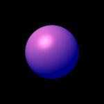 You should get a picture similar to the one
depicted left. So much trouble for a simple plastic ball? Don't worry, the biggest part of the program's source has been used for initialization purposes, which
is common for almost every project in higher languages. It would have been possible to make it quick&dirty, but a clean setup makes live much easier later, believe me!
Let's replace the plastic with metal:
You should get a picture similar to the one
depicted left. So much trouble for a simple plastic ball? Don't worry, the biggest part of the program's source has been used for initialization purposes, which
is common for almost every project in higher languages. It would have been possible to make it quick&dirty, but a clean setup makes live much easier later, believe me!
Let's replace the plastic with metal:
    list.Reset();
    list << "kr" << LfVector3(0.6,0.3,0.3);
    list << "kd" << 0.3;
    list << "km" << 0.3;
    list << "shinyness" << 0.8;
    list << "fresnel" << LfInt(1) << LfFloat(0.5) << LfFloat(0.5);
    list << "caustics" << LfInt(1) << LfInt(1);
    LfInt metal = s->NewMaterial("physical",list);

    list.Reset();
    list << "basis" << "sin";
    list << "scale" << 0.6;
    list << "depth" << 0.2;
    list << "turbulence.omega" << 0.5 << 0.7;
    list << "turbulence.octaves" << LfInt( 6 );
    LfInt bump = s->NewPattern( "multifractal", list );

    list.Reset();
    list << "kr" << LfVector3(0.3,0.3,0.5);
    list << "kd" << 0.3;
    list << "km" << 0.3;
    list << "shinyness" << 0.8;
    list << "fresnel" << LfInt(1) << LfFloat(0.5) << LfFloat(0.5);
    list << "caustics" << LfInt(1) << LfInt(1);
    list << "displacement" << bump;
    LfInt bumpmetal = s->NewMaterial("physical",list);
The first material, metal, is derived from the material class physical. Notice that even Fresnel's law will be taken into account (Lightflow has been
designed for scientific visualization!). The second material equals the first one with the addition of a displacement. Although surface displacement is being
supported by a lot of 3D programs (even by today's 3D graphic cards!) via bump mapping, Lightflow supports real surfaces. The next picture should
explain the differences:
Bump mapping pertubates the norm vectors of the surface; these vectors will be used in the local as well as in the global lightning model (remember your physics
lessons: reflection/refraction law!). The disadvantage of this technique: only the appereance of the surface, not the surface itself will be modified. A sphere
may look bumpy inside it's shape, but the shape itself remains a circle (in 2D projection). Wanna see a demonstration? Ok, OK lets create two balls: one ball using
bump mapping and one bumpy ball with a real surface. As I told you before all objects will be created
at the origin. So we have to perform a coordinate system translation if we would place the objects elsewhere. These translations are encapsulated by
LfTransform-objects (for the advantaged CG readers: they encapsulate the 4x4 transforming matrices). I defined an object of this type (trs)
at the beginning of the listing, behind the parameter container. It supports these basic geometric operations:
- Translation
- trs.Translation(LfVector3(x,y,z))
- Scaling
- trs.Scaling(LfVector3(xscale,yscale,zscale))
- Rotation
-
- around the x axis: trs.RotationAroundX(angle_in_radians)
- around the y axis: trs.RotationAroundY(angle_in_radians)
- around the z axis: trs.RotationAroundZ(angle_in_radians)
Complex operation have to be specified by nested transformation environments:
         s->TransformBegin(trs.Translation(LfVector3(-1.7,0,1.3)));
         s->TransformBegin(trs.RotationAroundZ(-1.5));
         ...
         s->TransformEnd();
         s->TransformEnd();
Back to the balls:
    // the next two are made from bump metal
    s->MaterialBegin(bumpmetal);
    // the first ball to the left should use bump mapping
    s->TransformBegin(trs.Translation(LfVector3(-1.7,0,1.3)));
    list.Reset();
    list << "radius" << 1.0;
    s->AddObject(s->NewObject("sphere",list));
    s->TransformEnd();
    s->TransformBegin(trs.Translation(LfVector3(1.7,0,1.3)));
    // ...a real surface!
    LfInt sphere = s->NewObject( "sphere",list);
    list.Reset();
    list << "surfaces" << sphere;
    list << "tolerance" << 0.02 << 0.1 << 0.05;
    s->AddObject( s->NewObject( "surface-engine", list ) );
    s->TransformEnd();
    s->MaterialEnd();
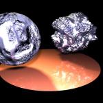 As you see from the picture at the left, the difference is indeed amazing. If you browse the mechanic-die example you'll see that these surfaces could be used
in boolean operations (CSG)! Oh, here the complete source for this picture.
As you see from the picture at the left, the difference is indeed amazing. If you browse the mechanic-die example you'll see that these surfaces could be used
in boolean operations (CSG)! Oh, here the complete source for this picture.
Flyby
The last thing I'm going to show you here (for now) will be the creation of animations. I'd chosen the last scene to start with. The goal: a camera fly-by
created as an MPEG. Lightflow itself doesn`t support video formats so I used convert for creating an mpeg movie from a list of Targa files.
 As you can see from the picture on the right, the camera should travel on a hemicircle continuously spotting at a point between our bumpy spheres.
Because having the mathematical operations of C/C++ available this is quite easy to obtain, as the source
shows. The makefile changed also, because the final goal is no longer a single picture but a whole anim. An additional clean target (call make clean)
will remove the temporary Targa files; the final Makefile here.
Puh, that was a lot of work... but it looks nice, doesn't it?
As you can see from the picture on the right, the camera should travel on a hemicircle continuously spotting at a point between our bumpy spheres.
Because having the mathematical operations of C/C++ available this is quite easy to obtain, as the source
shows. The makefile changed also, because the final goal is no longer a single picture but a whole anim. An additional clean target (call make clean)
will remove the temporary Targa files; the final Makefile here.
Puh, that was a lot of work... but it looks nice, doesn't it?
Conclusion
Lightflow is a very extraordinary program; the optical effects taken into account (caustics,Fresnel effect,non-isotropic surfaces,radiosity,...) plus the amount of
supported representations (euclidians, meshes,nurbs,bsplines,metaballs,...) and the concept of binding to object-oriented computer languages make it a superb
choice for scientific visualization purposes. It may be unfamiliar to use a renderer without GUI support, but several examples (e.g. LaTeX or Hollywood itself -
most 3D special effects have been created using batch-oriented renderers) shows that the concept of "programming" something will get superior over GUI-based
programs when considering bigger projects. IMHO this is a question of reusability (if you'd programmed a toon representation you can use it elsewhere), freedom & power
offered by computer languages (every GUI reduces the number of possible combinations) and the level of complexibility (you could write a class generating a
human-like object which accepts commands like "turn head" or so; later than you can instance 100 objects of this class and work with them on the abstract level of
human objects! (this approach has been used for the F/A-18 jets in "Independence day)). Hopefully I succeed in my approach to explain the basics of the
LightFlow C++ binding. You may continue with parsing the doc or may example scenes (especially the mechanic die and the recursive tree). LEARNING BY DOING!
 You should get a picture similar to the one
depicted left. So much trouble for a simple plastic ball? Don't worry, the biggest part of the program's source has been used for initialization purposes, which
is common for almost every project in higher languages. It would have been possible to make it quick&dirty, but a clean setup makes live much easier later, believe me!
Let's replace the plastic with metal:
You should get a picture similar to the one
depicted left. So much trouble for a simple plastic ball? Don't worry, the biggest part of the program's source has been used for initialization purposes, which
is common for almost every project in higher languages. It would have been possible to make it quick&dirty, but a clean setup makes live much easier later, believe me!
Let's replace the plastic with metal:
